There aren't many dirt riders who would dispute the fact that technology has been very good to them. We can buy motocross and off-road machines right off the showroom floor that are capable of virtual "Formula 1" performance. This translates into your being able to buy a CRF250R and race supercross or National motocross. Or you could take delivery of a CRF250X and race national enduros or GNCC races. But all technology comes with a price. Frankly, it is amazing that the manufacturers have gotten four-strokes to produce the power they currently do with astounding reliability. Imagine the care your truck's engine would require at 770 horsepower! But these new four-strokes are turning some dumfounding rpm numbers. The 250cc models are in the neighborhood of 13,000 rpm! That means the piston goes up and down more than 200 times a second! Not many engines can live at those rates, let alone live without care and maintenance. No matter which four-stroke you ride, there are some critical maintenance issues. These high-rpm engines need fresh oil frequently, and the valves' clearances must be checked often. If the valves get tight, expensive repair bills are not far away. Tight valve clearances mean the valve stem is stretching or (more likely) the head of the valve is growing soft and "sinking" into the head. So the valves do not close all the way, and the super-heated combustion gases are leaking between the valve and the seat. The sealing surface—which must be perfect for maximum power—is quickly damaged. If the correct clearances are maintained, the valves can give a long service life. The four CRF valves retail right at $187.48, and the head is $322.04—all the motivation you need to keep an eye on things. In the case of the CRF250R, the piston does need regular replacement, but it is less than $60, and rings are slightly more than $30. Having a piston fail at 13,000 rpm will lead to a repair bill that will make you lose your breakfast.The good news is the Honda CRF250R is extremely easy to work on. Any home wrench with a little talent, decent tools and the ability to follow direction should easily be able to freshen the top end of a CRF. The CRF450R is much the same, but the cam-bearing supports are not cast into the head as with the 250. If you can handle the top end on a power-valve two-stroke, the CRF should be no problem. Follow along as Honda's Eric Crippa rebuilds a CRF250R. This is a home garage, and Crippa used our tools for the job.
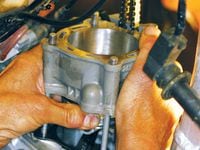
1. The first steps are to remove the seat and tank, so you can get at the cam cover. This is easy with T-handles and sockets, but it went really quickly with a Makita cordless impact driver. It isn't necessary to remove the radiators, but we took them off for more room and to make taking photos easier. You will need to drain the coolant, though, and draining the oil and changing the filter is a good idea. Naturally, you'll need to remove the headpipe and pull back the carburetor; it does not need to be removed from the frame.
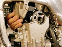
2. The cam cover removes easily up through the top of the frame. It has a rubber gasket that is reusable if you don't damage it. Take care popping loose the cover, and you should have no problem.
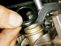
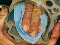
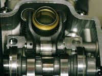
3. There is a passage cast into the cam cover and the cylinder head for the spark plug to go through. The passage is sealed with a reusable rubber seal between the head and cam cover. Take off that seal as soon as the cover comes off, so it isn't misplaced or, worse, knocked into the engine. Also, remove the spark plug at this time.
4. There are inspection covers on both sides of the engine at roughly crankshaft level. Remove both covers with the proper-size Allen wrench. Inspect the covers. The smaller one was cracked on our bike, and the flange broke clean away when we tried to tighten it.
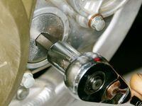
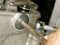
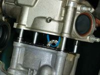
5. Once the covers are removed, turn the engine over slowly with the kickstart lever. It should turn over easily with the spark plug out. You want to line up the timing marks on the crank gear and the ignition rotor with corresponding marks (indicated with the pointer) on the engine covers. The marks align on both sides, but the drive side of the engine is easier to see.
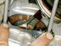
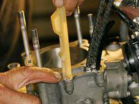
6. Next, remove the bolt from the back of the cam-chain tensioner. The Honda shop manual has a diagram you can follow to make this tool from sheet metal with a hacksaw and a flat file. Insert the tool into the back of the tensioner, rotate it counterclockwise to retract the tensioner, then push the tool in farther to lock the tensioner plunger back. You can leave the tensioner locked and in place if you are just doing a piston and rings replacement. You can use a small, flat-bladed screwdriver to wind the tensioner back, but you will have no way to lock it there. We found it easier to remove the tensioner from the cylinder. You are trying to create all the slack you can in the cam chain, and the automatic tensioner will keep trying to take up that slack.
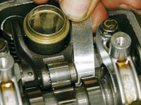
7. With the timing marks in the cases aligned, the timing lines on each side of the cam sprocket should be lined up parallel with the gasket surface. The lobes on the cam should be facing to the rear of the engine. If they are not, you need to rotate the engine one more turn and realign the timing marks. The crank turns over twice for every time the cam turns once, so the additional turn should line everything up.
8. This is the ideal time to check the valve clearances—before you loosen the cam-bearing caps. You won't be adjusting any of the clearances, just carefully measure and write down the numbers. Even if the valves are sealing perfectly, you will find that making adjustments while the head is off is the simplest method.
9. It doesn't matter whether you start on the intake or the exhaust side. If the clearances of any of the valves change radically or often, then the valves need replacement. If the clearances are overly tight, then the valve seats are most likely bad. The seats will need to be recut, but you can't have just any corner machine shop do the work. The seats should be cut only once. If valve problems persist, the head should be replaced.
10. If you are simply adjusting the valves, you may not need to remove the cam-bearing caps or the cam. If you need only to adjust the exhaust valves, you can remove the exhaust-side rocker arm after removing this cover on the side of the head. The rocker-arm shaft should slide right out after the front cam-bearing cap bolts are removed.
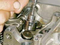
11. Remove the bolts that secure the cam-bearing caps. Hold each cap down low at the base and rock back and forth carefully to work it off the locating dowels.
12. There is a cam-bearing locating clip in the cap, and it can come loose and fall into the engine. Watch for it as the cap lifts, and make sure it doesn't drop out. Remove the clip and put it with the bearing caps in a resealable sandwich bag to make sure it doesn't get misplaced.
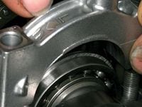
13. You need to keep the cam-bearing caps in the correct position, but they are marked on top to make it easier. Just be aware that they must go back on the same side, and facing the same direction that they faced when they came off.
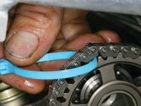
14. Put a zip-tie around the chain to keep track of it. With the tensioner locked back or removed, there should be sufficient play in the chain.
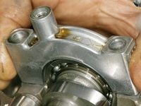
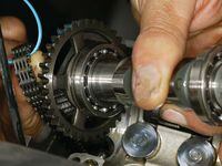
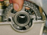
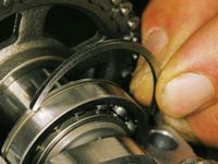
15. This is the single operation that is fairly unique to a four-stroke top end rebuild. Most bikes have removable cam sprockets, but the CRF250R and CRF250X do not. The only way to get enough slack in the chain to remove the cam is to slide the drive-side cam bearing toward the cam sprocket. The clip in the cam-bearing cap locks the bearing in place when the caps are on, but with them removed, the bearing should slide easily to the side. That will allow the cam to drop down and give enough play in the chain to remove it from the cam sprocket, and for the cam to come out of the engine.
16. Tilt the cam (throttle-side up, clutch-side low), and remove the chain with one finger. Let the cam chain drop into the head. It can't really go anywhere, but it is a good idea to keep your little brother from moving the kickstart lever.
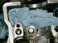
17. After the chain is down in the cam-chain tower, pack the top of the opening with a clean paper or cloth towel. The next steps will require removing small parts, and the cam-chain passage is a road straight into the crankshaft area for small parts. You don't want to go there.
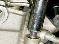
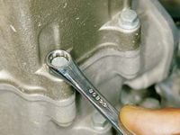
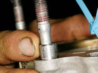
18. Remove the 14mm head nuts. Two are located externally, and two are located under the cam cover. They'll be tight, so use a quality socket with an extension.
19. A powerful telescoping magnet is the safest way to remove the inside nuts and washers.
20. The head has these smaller bolts that seal the engine on the outside of the cam-chain area. You'll need to remove them now. They are tough to reach with a socket, or even a ratcheting wrench.
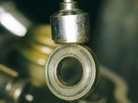
21. Before moving the head around, we chose to use our magnet to remove the valve buckets that slip over the springs of the intake valves.
22. Sometimes the actual valve-adjusting shim remains in the bucket, as shown here. Other times it remains seated on the stem of the valve. We labeled the cups (i.e., R. In.) with a permanent marker, then put the shim that belonged with that valve with the cup.
23. Our magnet also worked great to pull the shims out of the exhaust side. You want to keep these shims organized, so you know which side they came from. If the valve clearances are fine, you will need to return the shims to the proper valve. If the clearances are off, you will need to know which shim was where so you can compute the thickness of the replacement shim you'll need.
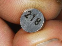
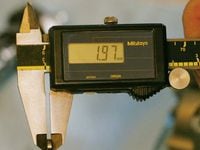
24. A new shim from Honda has the thickness printed on it in millimeters. This shim is 2.18mm.
25. The problem is that the printing wears off. You will need a quality caliper or a micrometer that reads in millimeters to determine the size of the shims that you take out of the engine. The micrometer is more accurate for this sort of measurement, but the caliper will do and is more useful when you're working on a dirt bike.
26. Now it's time to remove the cylinder head. If the gasket seal is stuck tight, check to make sure you have all the fasteners removed, then tap both sides of the head casting lightly with a rubber mallet.
27. Turn the head casting over and inspect the valves for any obvious flaws. If you have a solvent tank, add a couple of teaspoonfuls of solvent into the port on one side of the head. With the port up, so you don't dump the solvent, hold the head up to a good light and see if the valves remain fluid-tight. If the valves are not fluid-tight, the head needs a valve job or possibly even replacement. The darkened carbon around the valves tells us that our valves need replacing. Dump the solvent, turn the head over and repeat the test for the other two valves.
28. You'll need to remove the head gasket, then the white or neutral-colored cam-chain guide. The white cam-chain guide has a notch in the top surface of the cylinder for two nubs to ride in and a notch down in the cases for the bottom point to sit in, so check out how it looks and feels before you pull it out.
29. Note the two locating dowels in the top of the cylinder. Make sure you keep track of them, and don't let them get damaged.
30. Remove the cylinder. Note that the dowels are on the water-pump side of the engine.
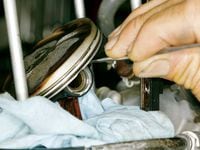
31. Stuff clean rags in the crankcase to keep the piston-pin circlips from falling in the engine. Use a strong, sharp tool to remove one circlip. We used a dental pick that we purchased from a tool store.
32. The head of an 8mm T-handle will push out the pin easily. Replace the piston every time you have the engine apart for any reason; they aren't that costly when you consider the price of the gaskets and other expenses involved in tearing down an engine. If the cylinder doesn't measure to specifications with a new piston, replace the cylinder or have it replated.
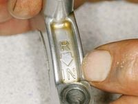
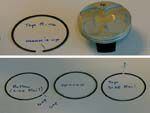
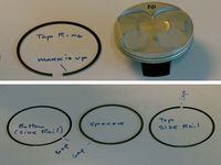
33. Be aware the piston has a definite direction in which it must be installed. The "IN" printed on top means put that side of the piston on the intake side of the engine. Insert one wrist-pin clip. Crippa inserts the pin and holds it short with one finger, then he pushes in the clip. The open ends of the clip should face either up or down, but not to the opening in the piston.
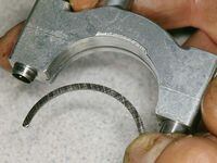
34. The manual specifies a direction of installation for each ring to stagger the ring ends. We laid the rings out in order to illustrate. Put the rings on with the marks stamped into their ends facing up. The oil "ring" consists of two side rails and a wavy spacer. The ends of the spacer butt up against each other. They shouldn't overlap or interlock.
35. Install the piston, slide in the pin until it seats on the side that has the clip installed and insert the final clip. You should always use new clips.
36. Remove the towels, then install the base gasket. Make sure the locating dowels are still in the correct locations and are installed properly. Clean the cylinder with contact cleaner on a paper towel, and follow all the directions in the service manual regarding measuring the cylinder bore and cleaning the oil passages and gasket surfaces.
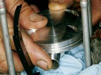
37. After the cylinder is clean, apply oil to it, the piston and the rings before assembly. You should be able to lower the cylinder with one hand while compressing the rings with the other. As the rings slide into the cutouts on the side of the cylinder, make sure they don't hang up on the edges. Do not force the cylinder or twist it while working the rings into the bore.
38. Slide the white cam-chain guide down into the cylinder. There is a notch in the case and cutouts in the top of the cylinder for the little locating nubs on the sides of the guide, and they both have to be engaged. Rock the guide back and forth to make sure it is seated correctly.
39. Install a new head gasket, and make sure the locating dowels are in place. The cutouts in the head gasket will not match the openings in the water jacket. Don't be tempted to change the size or location of the coolant holes in the gasket. Slide the head on, while pulling the cam chain up and out of the way with the zip-tie you put around it earlier, and pack paper towels into the cam-chain opening.
40. Install the washer and nuts that hold down the head, then torque all the head bolts to the correct specifications—29 foot-pounds for the four large nuts and 7 foot-pounds for the two smaller external bolts. The washers are shaped, so the narrow side faces the aluminum of the head. You should be able to tell which side has had a nut spinning against the surface. If the valves checked out, you should already have purchased whatever shims you need. If you had new valves installed, just install the original shims. You'll have to install the cam and rocker arm, torque the bearing caps and check the clearances, then remove the cam again if any shims need to be changed.
41. Install the intake shims and buckets; and if you have left the rocker arm in place, you'll also need to install the exhaust shims. Make sure the timing marks on the crank are still aligned, then start to install the cam chain on the cam sprocket. Slide the cam in with the lobes facing rearward.
42. Once the cam is in, don't worry if the cam chain is off a bit. With the play in the chain from the bearing being slid to one side, it is easy to "wrinkle" the cam chain to move it one tooth at a time. Move the chain tooth by tooth until you line up all the marks. Check your work twice here; a mistake can allow the valves to hit the piston.
43. After all the marks are lined up, slide over the cam-chain-side bearing. Align the retainer clip cut in the bearing with the bearing-cap bolt hole. If you have removed the rocker arm, it must be replaced now. Note that the shaft has holes in it through which the bearing-cap bolts go, so those holes must be indexed correctly before the bearing caps go on.
44. Mount the cam-bearing caps after removing the locating clips, putting a little grease on them and installing them into the bearings. It is less likely you will drop the little part in the engine that way.
45. Rock the caps around to make sure the bearing locating clips are lined up. Torque the bearing caps to 12 foot-pounds. At this point you must check the valve clearances again. If any are off, the cam must be removed and the correct shims installed. We replaced the valves on our bike, so we had to remove the cam and reshim the valves after assembly.
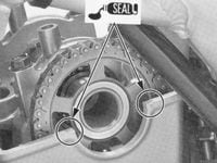
46. Install the seal at the plug tube and apply sealant as directed here, then replace the cam cover. All that remains is to button everything back up, put in coolant and oil and go for a break-in ride!

/cloudfront-us-east-1.images.arcpublishing.com/octane/X4HH3H6LWFEAXFAOS4D7WPCBGU.jpg)
/cloudfront-us-east-1.images.arcpublishing.com/octane/KIWKUCDIAZEDXBC53B4CL23XX4.jpg)
/cloudfront-us-east-1.images.arcpublishing.com/octane/Z7SDMK75WBCKPOECPH2ZZC3MSE.jpg)
/cloudfront-us-east-1.images.arcpublishing.com/octane/2D4H2OGFH5ABPA4WIRHNSMBER4.jpg)
/cloudfront-us-east-1.images.arcpublishing.com/octane/MNV7VIZGBZACLJBL2WV7WVO7VU.jpg)
/cloudfront-us-east-1.images.arcpublishing.com/octane/H3ANF3MCT5BONNQAQISDYEJA4I.JPG)
/cloudfront-us-east-1.images.arcpublishing.com/octane/J7F3JQP2OVDLXDZ7VBJDMVGB4A.jpg)
/cloudfront-us-east-1.images.arcpublishing.com/octane/D3SZKDPELNAKPNAQIHTLZRF5QM.jpg)
/cloudfront-us-east-1.images.arcpublishing.com/octane/H5VKBUL2Z5BYDAOQOUQAHKOTEU.jpg)
/cloudfront-us-east-1.images.arcpublishing.com/octane/C2HS5ADXIND7LBDK37LGI5RN4E.jpg)
/cloudfront-us-east-1.images.arcpublishing.com/octane/SCDNATMCERHOHPEVO3JPCS6M2Y.jpg)
/cloudfront-us-east-1.images.arcpublishing.com/octane/TOQ7IBXN2BAV5MELGO5Y3W64UE.jpg)
/cloudfront-us-east-1.images.arcpublishing.com/octane/CSQ5SXR2QZEYLIH4GZVFYPKXNU.jpg)
/cloudfront-us-east-1.images.arcpublishing.com/octane/MLARWRCDL5HH3FYTXFXK26ARF4.jpg)
/cloudfront-us-east-1.images.arcpublishing.com/octane/QHHRQIMLX5DQREULLI7LJT2WOM.jpg)
/cloudfront-us-east-1.images.arcpublishing.com/octane/2MFKDMEXI5A2PAB2BCLJ4TE6CI.jpg)
/cloudfront-us-east-1.images.arcpublishing.com/octane/BCRBSND54FE3BDDWWMPP6LWCAY.jpg)
/cloudfront-us-east-1.images.arcpublishing.com/octane/53OLCW5X45HRTLKV5OVHFCJSJA.jpg)
/cloudfront-us-east-1.images.arcpublishing.com/octane/PUS7VYTISVCVXGLWRGNHS7ZR4M.jpg)
/cloudfront-us-east-1.images.arcpublishing.com/octane/UO25RAAEQJDIVLNGY2L7S4IRDQ.jpg)
/cloudfront-us-east-1.images.arcpublishing.com/octane/3GQBZGCTXRE35IIIOI22RBQSOU.jpg)
/cloudfront-us-east-1.images.arcpublishing.com/octane/OIT4RWYSOJGOFJE2LLVSYGMRXY.jpg)
/cloudfront-us-east-1.images.arcpublishing.com/octane/Z4GKM7BKVBAKDBN37S5R4QR4LA.jpg)
/cloudfront-us-east-1.images.arcpublishing.com/octane/ZM6HFGPAQVDAHFMPXXKVCUMU2U.jpg)